
SWD Network Design (V2.4)
Overview
SWD Network Design is an automated engineering application for the hydraulic design of gravity stormwater drainage networks comprising up to 100 connected drain segments along a defined route. Unlike the earlier single-segment sizing version, the current application designs the drainage system progressively from the first upstream point to the final outfall.
The route is defined by point coordinates, tributary drainage areas, run-off coefficients and Finished Ground Levels (FGL). The Drain Invert Level (DIL) at the final outfall is supplied by the user as the fixed downstream boundary condition. The software then establishes the longitudinal drain profile, determines the discharge carried by each segment and sizes the drain sections using Manning’s equation.
Network-Based Design Methodology
- For each pair of consecutive route points, the software automatically:
- Calculates the drain segment length from the entered coordinates.
- Adds the tributary area entering the system at that point.
- Applies the run-off coefficient assigned to that tributary area.
- Accumulates the run-off weighted area, Sum(C x A), in the downstream direction.
- Calculates the required stormwater discharge for the segment from rainfall intensity and the accumulated run-off contribution.
- Maintains the adopted drain size as non-decreasing in the downstream direction.
Run-Off Coefficients for Varying Site Surfaces
Run-off coefficient is no longer treated as one common value for the complete drainage route. Each tributary area can be assigned its own surface/run-off coefficient, allowing paved, unpaved, gravel, concrete and other contributing surfaces to be represented independently. The resulting cumulative Sum(C x A) is used for segment-by-segment discharge calculations.
Outfall-Controlled Longitudinal Profile
The user provides the DIL at the final outfall rather than entering a drain slope as a design input. Together with the minimum permissible starting depth or buried-pipe requirement and the route geometry, the fixed outfall DIL is used to establish the gravity-flow longitudinal profile.
Intermediate invert levels are calculated automatically. At every point, the reported drain depth is the vertical difference between the local FGL and the calculated DIL. If an FGL is not provided, the software assumes 0.000 m.
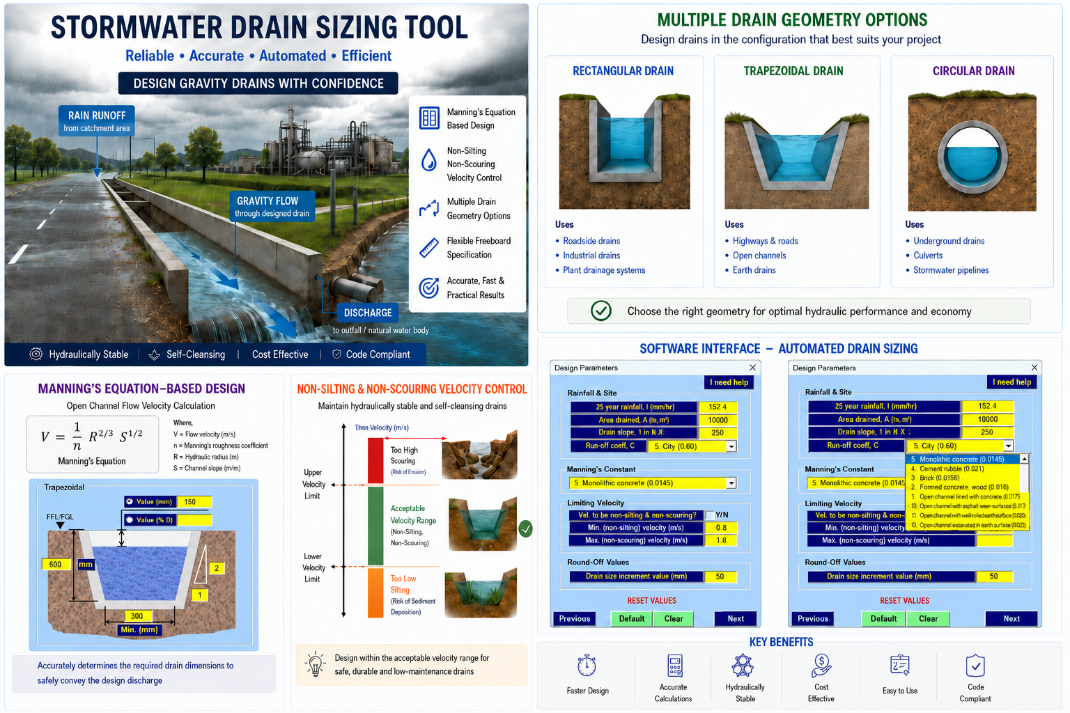
Manning’s Equation-Based Hydraulic Design
- Each segment is hydraulically evaluated using Manning’s equation. The design considers:
- Required segment discharge
- Manning’s roughness coefficient
- Calculated longitudinal gradient
- Hydraulic characteristics of the selected drain shape
- Flow area, wetted perimeter and hydraulic radius
- Resulting flow velocity and discharge capacity
- Supported Drain Configurations
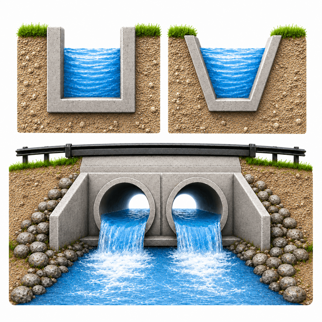
- The complete network may be designed using any one of the following drain configurations:
- Rectangular drains
- Trapezoidal drains
- Circular buried drain pipes
Rectangular and Trapezoidal Drain Sizing
For rectangular and trapezoidal drains, the entered overall depth is treated as the minimum permissible depth. The software increases the drain width as required to satisfy hydraulic capacity. For trapezoidal drains, the specified side slopes are retained during sizing. Once a larger drain size is required, a smaller size is not subsequently adopted downstream.
Circular Pipe Selection
For circular drains, the user selects minimum and maximum permitted pipe sections from the available pipe-size table, together with minimum soil cover and the maximum number of parallel pipes. Pipe internal diameter and wall thickness are obtained automatically from the selected sections.
The design starts with the smallest permitted pipe. Diameter is increased through the available sizes until the upper limit is reached. If additional capacity is required, the number of parallel pipes is increased and the diameter search restarts from the minimum permitted size. This process continues until the required capacity is achieved or the user-defined limits are exhausted.
Flexible Freeboard Specification
Freeboard may be specified either as a direct value or as a percentage of the applicable drain depth/pipe diameter. The selected freeboard is incorporated automatically in the hydraulic calculations.
Non-Silting and Non-Scouring Velocity Review
Users may optionally specify minimum non-silting and maximum non-scouring velocities. These limits are used as review criteria and do not force the software to alter the calculated drain gradient or prevent completion of the design. Where a calculated velocity lies outside the selected limits, an appropriate note is added to the output Remarks column for engineering review.
This approach allows flat gradients dictated by the available outfall invert level and site conditions to be reported without automatically modifying the hydraulic profile.
Automated and Efficient Network Design
- Key advantages of the revised application include:
- Design of up to 100 connected drain segments in a single run
- Automatic calculation of segment lengths from route coordinates
- Progressive accumulation of tributary run-off from differing surface types
Automatic discharge calculation for every drain segment
- Automatic downstream hydraulic sizing with non-decreasing drain sizes
- Outfall-controlled calculation of intermediate DILs and drain depths
- Reduced repetitive manual calculations and improved design consistency
Practical Engineering Output
The application produces a consolidated network summary together with sample design calculations for the final drain segment. The output includes:
- Route points and segment lengths
- Additional and cumulative tributary areas
- Run-off coefficients and cumulative run-off weighted areas
- Required discharge and available hydraulic capacity
- Selected drain width/depth or circular pipe arrangement
- Calculated longitudinal gradient and flow velocity
- FGL and Drain Invert Levels at segment ends
- Drain depths and engineering Remarks
- Sample Manning’s-equation design calculations for the last segment
Industry-Oriented Drainage Solution
SWD Network Design is intended for industrial plants, process and chemical facilities, infrastructure developments, municipal drainage, roads, commercial sites and other projects requiring systematic gravity stormwater drainage design along a defined route.
Salient Features
- Designs complete gravity stormwater drainage routes of up to 100 connected segments.
- Uses point coordinates to calculate individual drain segment lengths automatically.
- Allows separate run-off coefficients for individual tributary areas and accumulates Sum(C x A) downstream.
- Uses the user-specified final outfall DIL as the fixed downstream boundary condition.
- Calculates intermediate DILs, drain depths and longitudinal gradients automatically.
- Performs segment-by-segment hydraulic sizing using Manning’s equation.
- Supports rectangular, trapezoidal and circular drain configurations.
- Maintains non-decreasing drain sizes in the downstream direction.
- Selects circular pipe sizes from user-defined minimum and maximum limits and can adopt multiple parallel pipes.
- Accounts for minimum soil cover and pipe wall thickness for buried circular drains.
- Supports freeboard as either an absolute value or a percentage.
- Optionally flags velocities outside user-defined non-silting and non-scouring limits without forcing slope adjustment.
- Generates a consolidated network output summary and sample calculations for the final drain segment.

SWD Network Design (V2.4)
$ 24
: 12 Months
Ahmed Raza, Project Engineer, UAE –
We found this tool helpful for infrastructure and site development drainage design. It efficiently calculates required drain dimensions based on rainfall intensity, discharge, slope, and site parameters.
Srinivas Rao, Design Engineer – Civil, India –
The application makes stormwater drain sizing fast, systematic, and practical. It supports rectangular, trapezoidal, and circular drains with flexible freeboard and velocity limit inputs.
Thomas Green, Civil Engineer, UK –
SHEETFORGE Stormwater Drain is a very useful tool for designing gravity drainage systems. It uses Manning’s equation and helps arrive at safe drain sizes while controlling non-silting and non-scouring flow velocities.