
Steel Connection
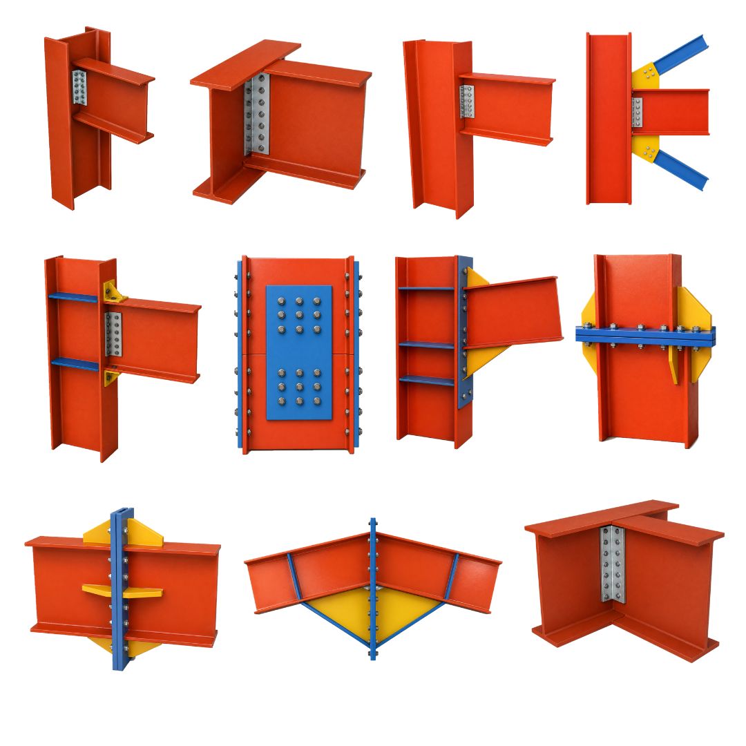
A1: BEAM TO COLUMN CONNECTION (SHEAR CONNECTION TYPE)
- Beam – Column Flange
- Beam – Column Web
A2: BEAM TO COLUMN CONNECTION (MOMENT CONNECTION TYPE)
- Beam – Column Flange
B: BEAM TO BEAM CONNECTION
- Shallow Beam – Deep Beam
- Beam –Beam Both of the same depth
C: COLUMN SPLICE CONNECTION
- Smaller column – Larger column
- Column – Column Both same size
D: BEAM SPLICE CONNECTION
- Beam – Beam Both same size
E: BRACING CONNECTION TO BEAM/ COLUMN
- Chevron bracing – Beam
A1: Beam to Column Connection — Shear Connection Type
- Beam to Column Flange
Overview:
This is a typical simple shear connection where the beam frames into the flange face of the column. It is generally designed to transfer vertical shear reaction, while allowing rotation at the beam end.
Typical bolted arrangements:
| Type | Description |
| Fin plate / shear tab | Single vertical plate attached to column flange, beam web bolted to plate |
| Double cleat angle | Two angles connecting beam web to column flange |
| End plate shear connection | Plate attached to beam end and bolted to column flange |
| Seated connection | Seat angle below beam with top angle for stability |
Salient features:
- Usually designed as a simple shear connection.
- Beam rotation is generally allowed, so it does not attract significant moment.
- The connection is mostly provided at the beam web zone.
- Bolts may be provided through a fin plate, partial depth end plate, or double cleat angles.
- Column flange should be checked for bolt bearing, local yielding, and possible stiffener requirement.
- Suitable where beam end moment is not intended to be transferred.
Important checks:
Bolt shear, bolt bearing, plate shear yielding/rupture, block shear, beam web bearing/tear-out, column flange local bending, edge distance, bolt pitch and erection clearance.
- Beam to Column Web
Overview:
Here the beam frames into the web side of the column, usually inside the column depth. It is also a simple shear connection, but detailing is more congested than beam-to-column-flange connection.
Typical bolted arrangements:
| Type | Description |
| Fin plate to column web | Plate fixed to column web – beam web bolted |
| Double cleat angles | Angles on beam web connected to column web |
| Partial depth end plate | Beam end plate bolted to column web |
| Full depth end plate | Larger end plate used where reaction is higher |
Salient features:
- More sensitive to column web strength and flexibility compared with column flange connection.
- Column web may require stiffeners if concentrated force is high.
- Bolt access should be checked carefully because the beam connects inside the web zone.
- Suitable for simple framing where the beam does not transfer moment.
Connection detailing should avoid clashes with opposite side beams.
Important Checks:
Column web local yielding, web crippling, web buckling, bolt access, beam setback, cope requirements, block shear, fin plate bending, and bolt group eccentricity.
A2: Beam to Column Connection — Moment Connection Type.
- Beam to Column Flange
Overview:
This is a moment-resisting beam-to-column connection. Unlike the shear connection, it transfers beam end moment + shear into the column flange. The beam flange forces are transferred through an end plate, flange plates, or haunch arrangement
Typical bolted arrangements:
| Type | Description |
| Flush end plate | Beam end plate within beam depth |
| Extended end plate | Plate extends beyond beam flange for extra bolt rows |
| Stiffened extended end plate | Extended plate with stiffeners to control prying and plate bending |
| Bolted flange plate connection | Top and bottom flange plates bolted to beam and column |
| Haunched end plate | Haunch below/above beam to increase moment capacity |
Salient features:
- Designed as a rigid or semi-rigid connection.
- Beam flanges transfer tension and compression forces due to moment.
- Beam web transfer’s vertical shear.
- Column flange and web may need continuity stiffeners or web doubler plates.
- Bolt rows are usually placed above and below the beam flanges in extended end plate connections.
- Connection must be checked for prying force, bolt tension, plate bending, column flange bending, and panel zone shear.
Important Checks:
End plate bending, bolt tension, bolt shear, combined bolt tension-shear, prying action, beam flange/web strength, column flange bending, column web yielding/crippling, panel zone shear, continuity stiffeners, doubler plates, and welds between end plate and beam if shop welded.
B: Beam to Beam Connection
- Shallow Beam to Deep Beam
Overview:
A secondary shallow beam frames into the web of a deeper primary beam. This is usually a simple shear connection. The shallow beam may be coped at top and/or bottom to fit inside the deeper beam.
Typical bolted arrangements:
| Type | Description |
| Fin plate | Plate fixed to deep beam web; shallow beam web bolted |
| Double angle cleat | Angles connecting shallow beam web to deep beam web |
| End plate | Plate at shallow beam end bolted to deep beam web |
| Seated connection | Seat angle supports shallow beam bottom flange |
Salient features:
- The shallow beam usually frames into the web of the deeper beam.
- The top flanges may be kept at the same level for floor/deck support.
- The shallow beam bottom flange will usually be above the deep beam bottom flange.
- Connection is generally designed for shear only.
- Deep beam web should be checked for local bearing, crippling, and block shear.
- Stiffeners may be needed on the deep beam web if reaction is high.
- Seat angle can be used to ease erection and support the shallow beam during installation.
Important checks:
Coped beam strength, web local buckling at cope, block shear, bolt shear, fin plate bending, primary beam web local yielding, beam web bearing and erection clearance.
- Beam to Beam — Same Depth
Overview:
Two beams of the same depth are connected end-to-end or side-to-web depending on framing geometry. When both beams are same depth and one frames into the other, detailing is more difficult because flanges clash.
Typical bolted arrangements:
| Type | Description |
| End plate shear connection | End plate on secondary beam bolted to main beam web |
| Double cleat angle | Angles on both sides of beam web |
| Fin plate | Single plate connection where access permits |
| Seated connection | Seat angle below with top stabilizing angle |
Salient features:
- When both beams are the same depth, flange clashes must be carefully avoided.
- Beam coping may be required to clear the supporting beam flange.
- Simple beam-to-beam connections commonly use fin plates or double angles.
- Moment-type beam-to-beam connections require flange plates or extended end plates.
- Top flange alignment is important where decking or slab rests on the beams.
- Web local buckling and bolt group eccentricity should be checked.
Important checks:
Flange clash, beam coping, web connection eccentricity, bolt access, bolt group shear, block shear, supporting beam web yielding, and erection tolerance.
C: Column Splice Connection
- Smaller Column to Larger Column
Overview:
This is a vertical splice where a smaller upper column is connected to a larger lower column. Load transfer may include axial compression, axial tension, shear, and bending moment, depending on frame action.
Typical bolted arrangements:
| Type | Description |
| Flange splice plates | Plates bolted across column flanges |
| Web splice plates | Plates bolted across column webs |
| Bearing splice | Column ends machined or detailed for bearing with bolts for stability |
| Transition plate | Plate used where column sizes differ significantly |
Salient features:
- Load transfers from smaller upper column into larger lower column.
- Difference in flange width and depth requires proper load path detailing.
- Packing plates or transition plates may be needed.
- Bearing contact between column ends is important for compression transfer.
- Bolts and splice plates transfer tension, shear, and erection forces.
- Stiffeners may be required in the larger column to distribute load.
- Alignment of column centrelines is critical.
Important checks:
Axial compression bearing, bolt shear/tension, flange plate tension, web plate shear, column local bearing, eccentricity due to size change, erection stability, and continuity of centroid/load path.
- Column to Column — Same Size
Overview:
This is a direct column splice between two columns of the same profile. It is generally simpler than a smaller-to-larger column splice because the flanges and webs align.
Typical bolted arrangements:
| Type | Description |
| Flange splice plates | Outside or inside flange plates bolted to both column segments |
| Web splice plates | One or two web plates bolted across splice |
| Bearing splice | Compression transferred by direct bearing, bolts provide alignment and tension resistance |
Salient features:
- Simpler than unequal column splice because section geometry is same.
- Flange plates mainly resist axial force and bending moment.
- Web plates mainly resist shear and assist in axial transfer.
- Column ends may be milled or prepared for bearing.
- Bolts are designed for axial tension/compression effects, shear, and moment.
- Splice is usually located slightly above floor level for ease of erection.
- Temporary erection bolts may be used before final tightening.
Important checks:
Flange splice tension/compression, web splice shear, bolt group strength, bearing at milled ends, column slenderness during erection, splice location, and minimum splice plate thickness.
D: Beam Splice Connection
- Beam to Beam — Same Size
Overview:
A beam splice connects two beam segments in line. It may be designed as a shear splice only or as a full moment splice, depending on location and structural requirement.
Typical bolted arrangements:
| Type | Description |
| Web splice plates | Plates on one or both sides of beam web for shear |
| Flange splice plates | Top and bottom flange plates for moment transfer |
| Full bolted splice | Web + flange splice plates |
| End plate splice | End plates bolted together at beam ends |
Salient features:
- Flange splice plates transfer bending moment.
- Web splice plates transfer vertical shear.
- Splice location is preferably selected where bending moment is lower, unless full-strength splice is required.
- Top and bottom flange plates are usually provided symmetrically.
- Web splice plates are placed on one or both sides of the web.
- Bolt slip, bearing, block shear, plate rupture, and net section should be checked.
- Splice should be detailed to allow easy erection and bolt tightening.
Important Checks:
Flange plate tension/compression, bolt shear/tension, web shear, slip-critical requirement if movement is critical, block shear, plate net section rupture, and bolt hole deductions
E: Bracing Connection to Beam / Column
- Chevron Bracing to Beam
Overview:
Chevron bracing has two diagonal braces meeting at a beam, usually forming an inverted V or V shape. The brace forces are transferred into the beam through a gusset plate connection.
Typical bolted arrangements:
| Type | Description |
| Central gusset plate | Both braces bolted to a common gusset |
| End plate to brace | Brace end plate bolted to gusset |
| Cleat angle brace connection | Angles connecting brace to gusset |
| Beam stiffened gusset | Gusset connected near beam with stiffeners if required |
Salient features:
- Braces transfer axial force to a central gusset plate connected to the beam.
- Connection must handle both tension and compression brace forces.
- The beam receives vertical and horizontal components from the braces.
- If one brace buckles in compression, the other brace may create unbalanced force on the beam.
- Gusset plate thickness, bolt group, block shear, net section rupture, and weld/bolt capacity should be checked.
- Beam web or flange may require stiffeners at the brace intersection point.
- Gusset plate geometry should allow brace rotation and avoid premature buckling.
- Connection eccentricity should be minimized.
Important Checks:
Brace axial force, gusset plate yielding/buckling, Whitmore section, block shear, bolt shear/bearing, gusset-to-beam force transfer, beam local bending, and unbalanced vertical load on beam.
Reviews
There are no reviews yet.